There are four settings available for Transfer Fields to Design Using.
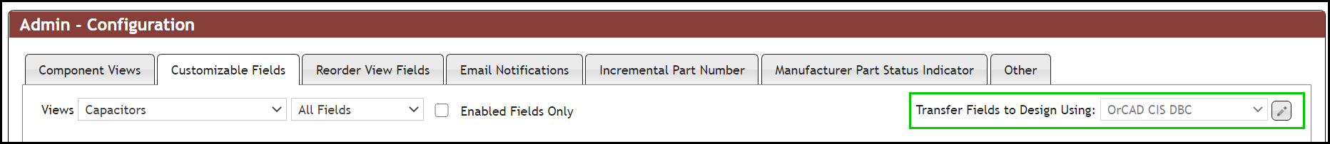
•OrCAD CIS DBC - This is the default out of the box configuration. When placing parts from CIP, the CIP OrCAD client plug-in will use the DBC file configured is CIS Configuration to determine the fields that will be transferred to the design. With this setting, your Capture.ini file must contain the Configuration File path and name. The CIP Client Installation Guide includes information to help you set up your Capture.ini file. With this configuration, the Schematic Part (OrCAD Symbol name) field is enabled for use with Capture CIS. The System Capture Part field is disabled as well as the System Capture Tab.
•OrCAD Using CIP - When placing parts from CIP, the CIP OrCAD client plug-in will transfer fields configured in the Customizable Fields tab. The DBC file will not be used by the OrCAD Client plug-in. With this configuration, the Schematic Part (OrCAD Symbol name) field is enabled for use with Capture CIS. Transfer to Design and Property Visibility columns are enabled for configuration. The System Capture Part field is disabled as well as the System Capture Tab.
•System Capture - When placing parts from CIP, the CIP System Capture client plug-in will transfer fields configured in the Customizable Fields tab. With this configuration, the System Capture Part field is enabled for use with System Capture. The System Capture tab is enabled.Transfer to Design, Property Visibility and System Capture Key Property columns are enabled for configuration. The Schematic Part (OrCAD Symbol name) field is disabled. Configured fields will be added to the PTF file during generation.
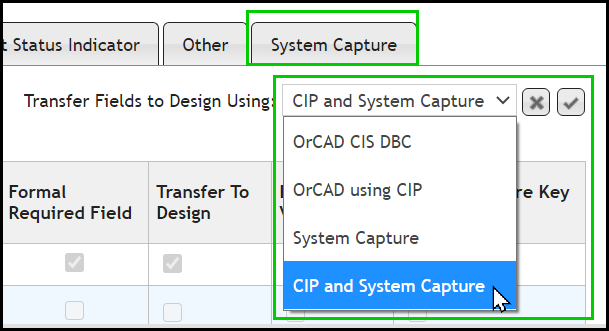
•CIP and System Capture - When placing parts from CIP, both CIP System Capture and OrCAD client plug-ins will transfer fields configured in the Customizable Fields tab. With this configuration, the System Capture Part Field is enabled for use with System Capture. The System Capture tab is enabled. Transfer to Design, Property Visibility and System Capture Key Property columns are enabled for configuration. Configured fields will be added to the PTF file during generation. Both Schematic Part and System Capture Part fields are enabled.
To change the Transfer Fields to Design Using settings,, click on the Edit ![]() button. When the System Capture or the CIP and System Capture options are selected, the System Capture tab will appear.
button. When the System Capture or the CIP and System Capture options are selected, the System Capture tab will appear.
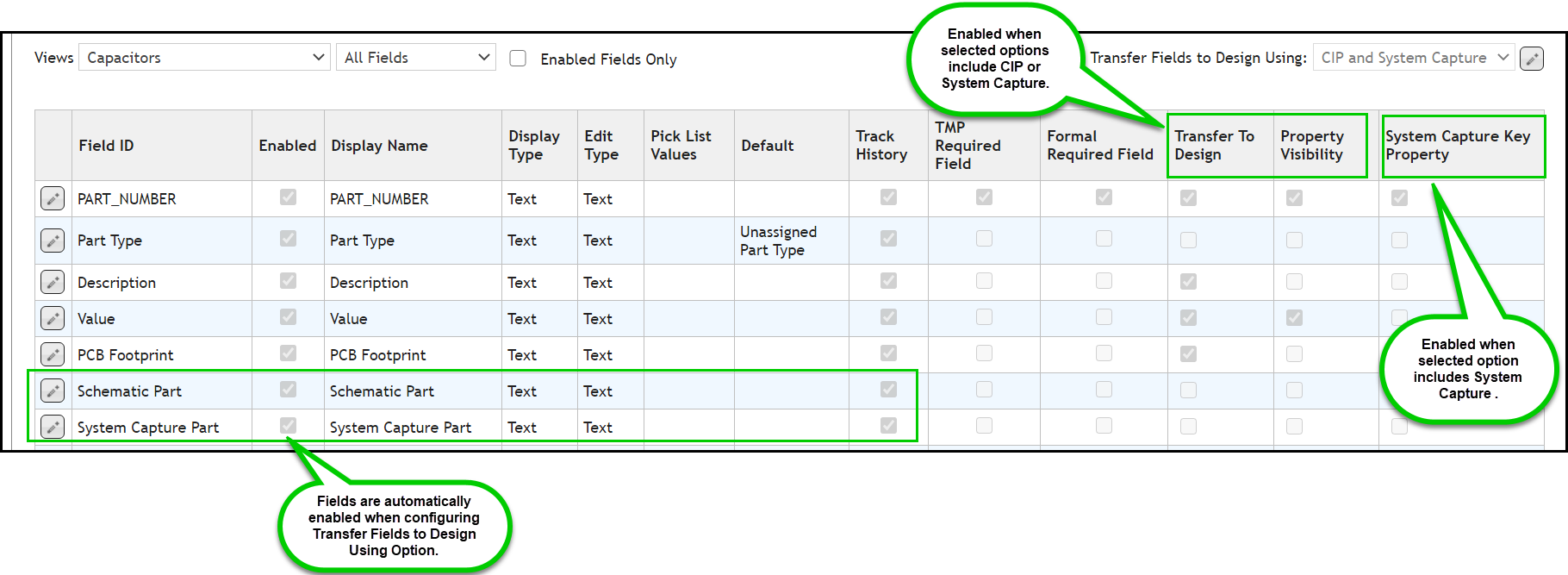
Click the Save ![]() button to start configuring Transfer to Design, Property Visibility and System Capture Key Property settings.
button to start configuring Transfer to Design, Property Visibility and System Capture Key Property settings.
To customize a field, select the Edit button ![]() and modify the desired fields.
and modify the desired fields.
If you want to transfer the value of a field to the symbol when placing a part, you can enable the Transfer to Design by selecting the checkbox.
If you want the value of a field to be visible after being placed onto a design, you can enable the Property Visibility by selecting the checkbox.
For System Capture Parts, if you want make a field a key property, you can enable the System Capture Key Property by selecting the checkbox. CIP will generate the PTF file with fields with this designation as key properties.