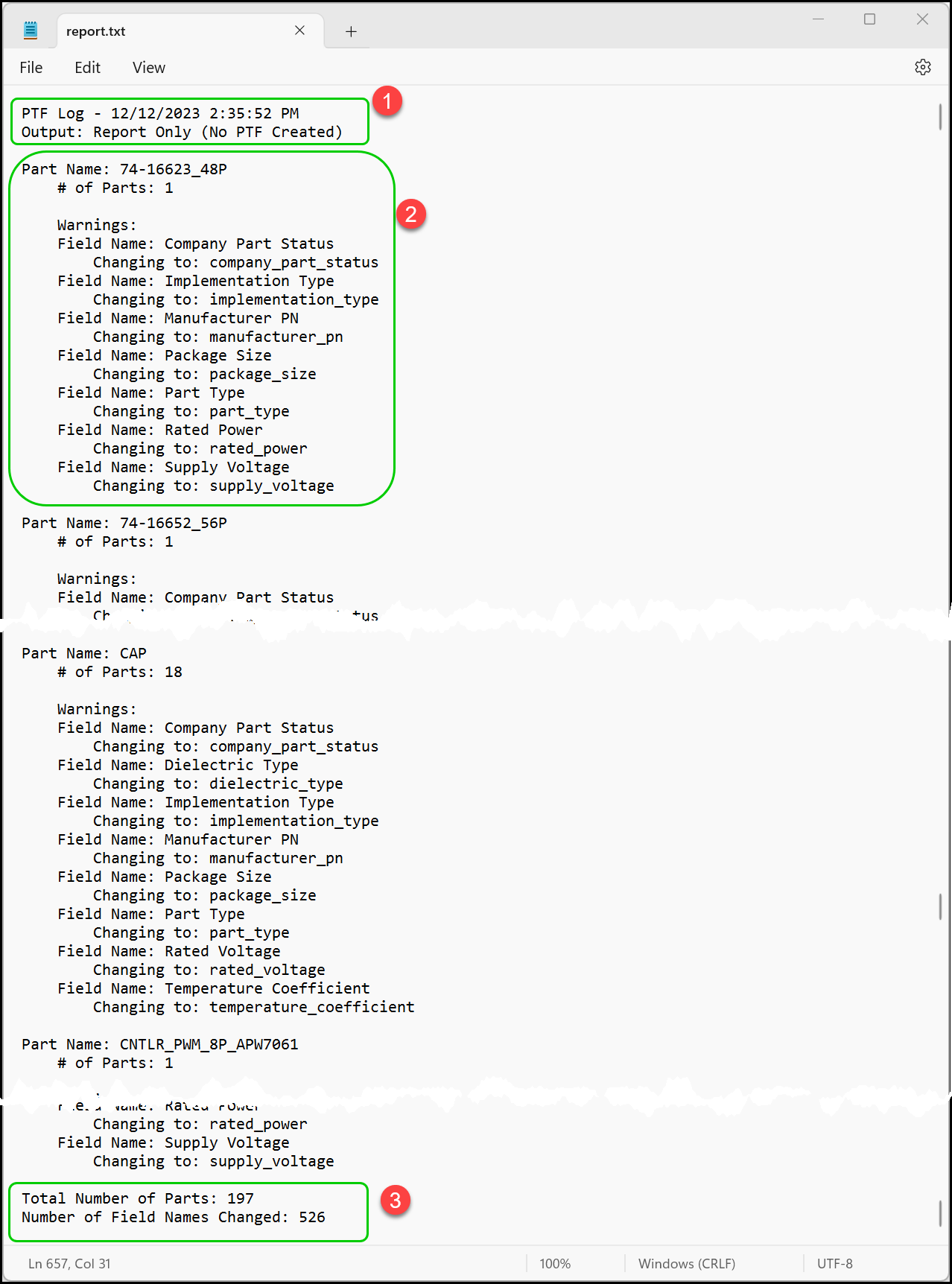
CIP creates a report consisting of number of parts per System Capture Part along with the substitution rules applied. When running Report from a standard browser, you can save the report to review using notepad or another text editor.
There are three sections in the Report.
1.Header
a.PTF Log - Consists of the date and time that this report is run.
b.Output: Contains the location of the PTF file when the Generate is used.
2.Part Information - This section is repeated for each System Capture Part Name
a.Part Name - This is the symbol name in the System Capture Part field. All parts with the same part name are grouped together per PTF format specification for DE-HDL.
b.# of Parts - Shows the number of parts found using this part name. TMP parts are excluded.
c.Warnings - Identifies any substitution rules applied for the Part Name.
3.Summary
a.Total Number of Parts - This is the number of parts that will be in the PTF file. TMP parts are excluded from the PTF file.
b.Number of Fields Changed - Total number of fields where substitution rules were applied.

Finding and Fixing Errors in Report
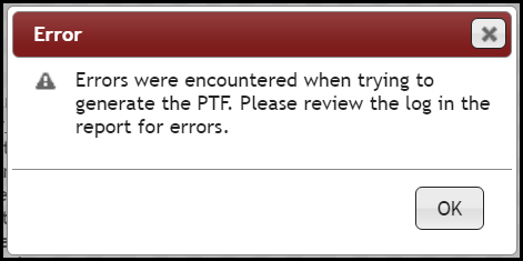
An error message displays when errors are found during report generation.

You will need to locate the source of the problem and fix before PTF Generation.
1.Click OK to dismiss error message.
2.Type Control F to locate "error" in the report.
3.Review the Part Names showing error.

Sample Error in Report
4.In this example, the Part Name, "BJT_NPN_BEC" is found in both ICs and Transistors views. However, there is a conflict (highlighted in pink) with fields defined for transfer to design between each of these views. To fix this problem, you can change the fields for transfer to design to match or change the Part Name for one of these parts.